🦀 🥧 rusty-pi 01: Blinky
Blinky 💡, the Hello World of embedded programming!
Development Environment & Platform
My development machine is an x86 Linux PC. Specifically, I’m using Linux Mint, which is based on Ubuntu if you’re not familiar with the distro. Your Mac milage may vary.
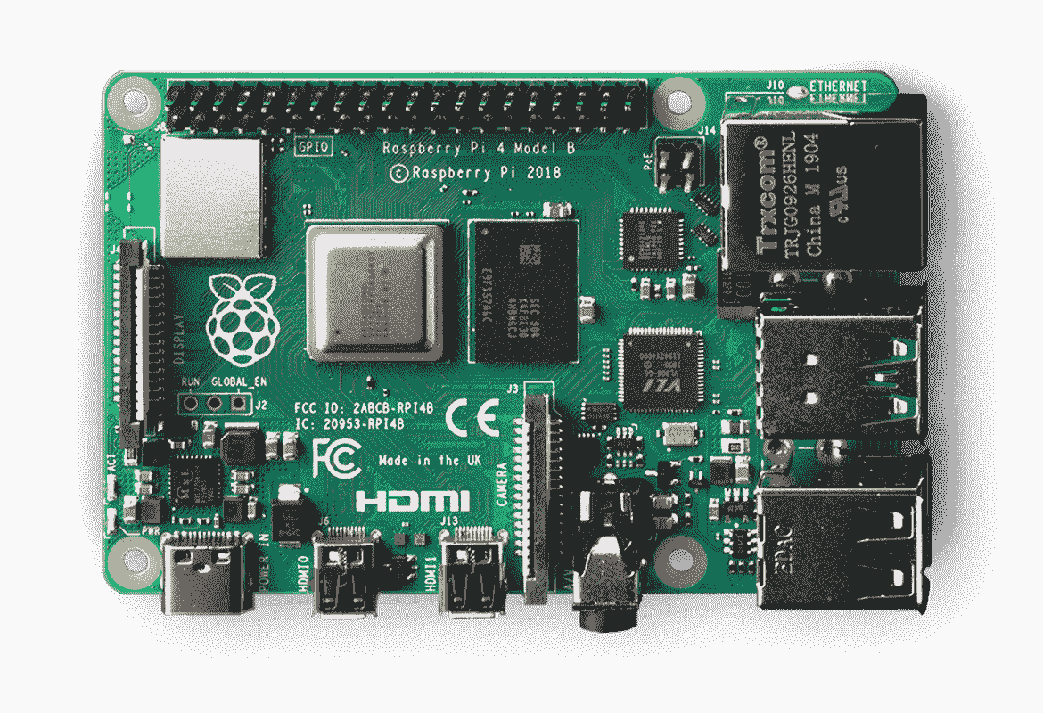 Source: newark.com/buy-raspberry-pi
Our target platform is the Raspberry Pi 4B. It has a BCM2711 SoC and ARM Cortex-A72 processor. Since we’re doing baremetal programming, it’s important to be cognizant of the hardware we’re interfacing with. We will see why very soon!
We’re going to use Rust to develop the software for our Pi. It has very interesting features for static analysis, memory allocation, C interoperability, and more that makes it suitable for systems programming.
In my writing, I’m assuming you have programmed baremetal (register-level)before on another platform like the STM32 or even Arduino.
Boot Process
The boot flow is documented well at Raspberry Pi’s own website. Check it out here! To get blinky working, we’re imaging the micro SD card with a pre-existing OS and then overwriting the kernel with our custom kernel, so the loading the firmware and bootloader is handled for us. I made this choice for the sake of simplicity and will go into this deeper in future milestones.
You won’t need it to reproduce this tutorial, but you can find the firmware and bootloader at raspberrypi/firmware.
Setting up the environment
First, install Rust. You can find the official instructions here.
Then, you’ll need cargo-binutils. We will use the rust-objcopy tool within it to convert the ELF output file of the rustc compiler to an img binary. You can install this with cargo:
cargo install cargo-binutils
That’s pretty much it! Now clone the a-vinod/rusty-pi repository and go to the 01_blinky subdirectory.
git clone git@github.com:a-vinod/rusty-pi.git
cd 01_blinky
src/boot.S
First check out the boot.S file in src. This will run first in our program and perform some initialization steps.
_start:
	mrs         x0, MPIDR_EL1
	and         x0, x1, #3
	cbnz        x0, halt

	ldr         x1, =__bss_start
	ldr         x2, =__bss_end

clear_bss_loop:
	cmp 	    x1, x2
	beq         boot_kernel

	stp         xzr, xzr, [x1], #16
	bne         clear_bss_loop

boot_kernel:
	mov         sp, #0x80000
	b           _start_kernel

halt:
	wfe
	b           halt
For 64-bit operation, registers start with x.
In the first section, we’re loading the data from MPIDR_EL1 to x0. The 2 least significant bits from this register can be used to identify the core that’s running the program.
| MPIDR_EL1[1:0] | Core Id |
|---|---|
| 0b00 | 0 |
| 0b01 | 1 |
| 0b10 | 2 |
| 0b11 | 3 |
That’s why in the second line of the program, we mask the register with 0x03, or 0b11. This will extract the code id into x0. For this program, we will only use core 0 so we send all other cores to halt.
The clear_bss_loop starts by comparing the addresses stored at x1 and x2, which are initially __bss_start and __bss_end. We define these addresses in the linker that we will go over layer and store the zero register (xzr) in 16-byte intervals until the block is zeroed out.
For now, just remember there is a block of memory that we need to set aside for the BSS, statically allocated variables in our program that aren’t assigned a value. For example, if we do something like int i; in C/C++. However, this isn’t commonly done in Rust.
The boot_kernel step initializes the stack pointer to 0x80000. This is necessary for the kernel to boot in 64-bit mode. Then it branches into _start_kernel. Now we enter Rust!
src/main.rs
#![no_std]
#![no_main]

use core::panic::PanicInfo;

use core::arch::global_asm;
global_asm!(
    include_str!("boot.S"),
);

pub extern "C" fn _start_kernel() -> ! {
    const PBASE:*mut u32            = 0xFE00_0000 as *mut u32;

    const P_GPIO_OFFSET:isize       = 0x8_0000;
    const GPIO_GPFSEL1_OFFSET:isize = 0x2;
    const GPIO_GPSET0_OFFSET:isize  = 0x7;
    const GPIO_GPCLR0_OFFSET:isize  = 0xA;

    unsafe {
        let p_gpio:*mut u32           = PBASE.offset(P_GPIO_OFFSET);
        let p_gpio_gpfsel1:*mut u32   = p_gpio.offset(GPIO_GPFSEL1_OFFSET);
        let p_gpio_gpset0:*mut u32    = p_gpio.offset(GPIO_GPSET0_OFFSET);
        let p_gpio_gpclr0:*mut u32    = p_gpio.offset(GPIO_GPCLR0_OFFSET);

        core::ptr::write_volatile(p_gpio_gpfsel1, 1 << 3);

        loop {
            core::ptr::write_volatile(p_gpio_gpset0, 1 << 21);
            for _ in 0..5000000 {
                core::arch::asm!("nop");
            }

            core::ptr::write_volatile(p_gpio_gpclr0, 1 << 21);
            for _ in 0..5000000 {
                core::arch::asm!("nop");
            }
        }
    }
}

// Called on panic
#[panic_handler]
fn panic(_info: &PanicInfo) -> ! {
    loop {}
}
The #![no_std] attribute is so that Rust doesn’t load the std crate and uses core instead. This is because std is meant to run on top of an OS, and core can run on baremetal. And we use #![no_main] because _start_kernel is called by boot.S directly, so we don’t use Rust’s normal execution flow. Check out this and this for more info on how Rust runs on baremetal platforms without underlying operating systems.
The _start_kernel function itself is very simple since we’re just doing a blinky. The code should look very similar to a blinky implementation in C/C++ for STM32 or Arduino. The objective is to set one of the GPIO pins as an output pin, and repeatedly set/clear it so that it blinks. The tricky part was actually getting the right base memory address!
Converting Address Spaces
On the BCM2711 doc, we can find the GPIO register address and offsets at section 5.2. Register View. Here, it specifies the GPIO base address as 0x7e200000. But in our code. But we can’t use this address (directly)!
Check out the address maps from the doc:
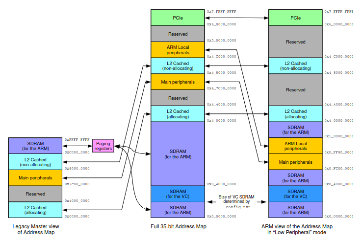 Figure 1: BCM2711 Address Maps
The 0x7e200000 address specified is actually the legacy address, not the address that our processor can see. What we really want is what 0x7e200000 maps to in the ARM view in Low-Peripheral Mode. The Raspberry Pi 4B boots into Low-Peripheral Mode by default unless specified otherwise in the config.txt file as a part of its boot process.
§1.2.4. Legacy master addresses
A peripheral described in this document as being at legacy address 0x7Enn_nnnn is available in the 35-bit address space at 0x4_7Enn_nnnn, and visible to the ARM at 0x0_FEnn_nnnn if Low Peripheral mode is enabled
So instead of 0x7e000000 as our peripheral base address, we will use 0xFE000000. And to avoid doing manual pointer arithmetic, we will use Rust’s pointer offset function to dynamically determine the addresses we are going to use based on the peripheral base address.
Calculating Address Offsets
The GPIO legacy master address is 0x7e200000, so the offset is 0x200000. The pointer type we use is mut* u32, so the size of the type that the pointer points to (u32) is 4 bytes. To offset 0x200000 bytes, we need to divide it by 4 before passing it in because the offset function will multiply the offset argument by the size of the calling pointer. For the same reason, we need to divide the offset for the GPFSEL1, GPSET0, and GPCLR0 offsets as well.
Panic Handler
The panic handler is a required function for #![no_std] like ours so we need to define one. We just put the process in an infinite loop in the event of a panic, which is fine here since it’s a very simple program.
linker.ld
The linker is a very important component because it defines the format of the ELF executable that the compiler will produce. We will define the text, data, BSS, and other segments of the program.
ENTRY(_start)

SECTIONS
{
    . =  0x80000;
    .text :
    {
        KEEP(*(.text._start))
        *(.text._start_kernel)
        *(.text*)
    }

    .rodata : ALIGN(8)
    {
        *(.rodata*)
    }

    .data :
    {
        *(.data*)
    }

    .bss : ALIGN(16)
    {
        __bss_start = .;
        *(.bss*);
        . = ALIGN(16);
        __bss_end = .;
    }
}
You’ll see each of the segments I mentioned defined above in the linker script. The ENTRY call tells the compiler that we want to start our program at the _start point of our assembly program. You may have noticed the . = 0x80000; with the 0x80000 address we initialized the stack pointer to earlier. The ALIGN() function is used to align the boundaries of each segment.
Since this is such a simple program, I didn’t worry too much about the values and used common values I found online. In short, this script is used by the compiler to structure the final executable.
Generating the ELF
Now, we will take use the rustc compiler to compile our Rust program (including the assembly boot.S) and use our custom linker script to structure the executable. Here is the full command:
RUSTFLAGS="-C target-cpu=cortex-a72 -C link-arg=--library-path=$(shell pwd)/../01_blinky -C link-arg=--script=linker.ld -D warnings" cargo rustc --target=aarch64-unknown-none --release
These are the important flags for the compiler:
target-cpu=cortex-a72: identifies the target CPUlink-arg=--library-path=$(shell pwd)/../01_blinky: source directory of linker scriptlink-arg=--script=linker.ld: linker script file nametarget=aarch64-unknown-none: cross-compile target for a baremetal environment and no specified vendor.
This generates the ELF executable in target/aarch64-unknown-none/release/rusty-pi.
Generating the .img binary
Finally, we convert the ELF executable to the binary using objcopy. Here is the command:
rust-objcopy -O binary target/aarch64-unknown-none/release/rusty-pi kernel8.img
That’s all! We’ve created baremetal blinky with Rust! 🦀
From the 01_blinky directory, it’s very easy to reproduce my results. The README has all the instructions for wiring and formatting the microSD card along with a Makefile to handle compilation. I encourage you to make a GitHub issue if you have any questions.
Next is UART!